F1 - PCIe/104 Rugged Modular Avionics Computer

Core i7 Rugged Military COTS Computer - PCIe/104 Rugged Modular Avionics Computer
Small Form Factor (SFF) with PCIe/104 Architecture
- Rugged COTS computer with Intel®3rd generation Core- i7 processor
- NVIDIA®GPU GT730M supports CUDA 384 independent displays by 4 x DP
- Modular rugged chassis with stackable PCIe/104 I/O card expansion.
- 28V DC MIL-STD-1275/704 Power supply with Voltage transient protections
- Design for reliability under demanding MIL-STD-810G Thermal Shock, Vibration, Humidity/EMI/EMC conditions
- Rugged IP65 aluminum chassis
- M12 connector
- Operating temperature range : -40°C to 75°C
Download
- Technical Profile
- Specifications
- CPU Performance
- SSD Performance
- Thermal Solution
- Introduction
-
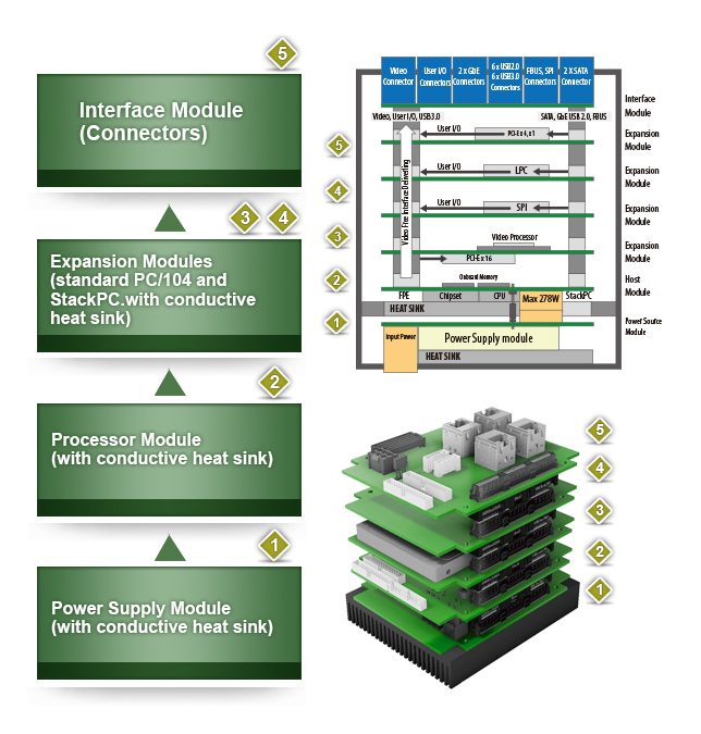
The purpose of PCIe/104 is to provide a System level Stack-Up Only approach. Specification adopts PCI-Express, Ethernet, SATA, USB as well as LPC, SPI, Field Buses and Common Power Connector to the any stacked architecture.
StackPC Specification defines StackPC, FPE, StackPWR connectors relative position and stacked systems organization common approach. Also specification describes using stack modules in COM applications.
Specification is targeted not only for traditional stackable systems with all boards of the same form factor, but also for other stackable architectures like COM applications (mezzanine Computer-On-Module in conjunction with base board) and SBC expansion (expansion bus for Single Board Computers of various form factors).
PCI Express was chosen because of its performance, scalability and wide market acceptance. Ethernet was chosen as the most popular long distance data interconnect, which is inevitable in modern computer based environments. SATA was chosen as the storage interconnect because of wide acceptance and bandwidth scalability. LPC bus, SPI and other signaling interfaces were chosen because of their capabilities to provide support for legacy devices and to expand host processor functionality in simple and cost effective way.
Additionally specification describes adoption StackPC to popular standards such as PC/104, 3.5 inch, EPIC and EBX. This adoption is as result of StackPC and PCIe/104 compatibility with Bank1 signals (same connector and similar pinout).
StackPC specification is designed to deal with challenges caused by modern point-to-point high speed serial interfaces to stackable architecture which used to rely on traditional parallel bus interfaces. New specification is suitable for using for SBC expansion and fully opens Computer On Module like area of applications. It also paves the way for using even higher speed interfaces which are just emerging on embedded arena.
Compared to past years systems, modern embedded solutions require support for greater number of input/output interfaces. With each year, new processor modules support more and more input/output interfaces integrated in system logic. This makes necessary to place additional interface connectors on processor and peripheral modules. Compactness of Small Form Factor modules is an impediment to placement of necessary components and sufficient number of input/output connectors. It should be noted, that stackable modules are mostly designed for harsh environments and require installation inside an enclosure to protect them from mechanical impact or corrosive substances. Hence, embedded systems manufacturers have to resort to various tricks to bring out all interfaces to connectors on the front panel of the enclosure using flat cables.
One of the solutions can be to aggregate the main set of input/output interfaces at the stack connectors. This allows to avoid some interface connectors (usually pin headers) and to provide more space on the module for placement of necessary components. This, in turn, leads to reduction of manufacturing cost and adds flexibility in terms of using the module in applications requiring limited functionality. Reducing cabling inside the enclosure improves convection, reduces magnetic noise pickup, and consequently, increases system effectiveness. Interfaces aggregated at the stack connectors can be led out of the enclosure using inexpensive and efficient solution – terminal interface module carrying the necessary set of standard interface connectors.
One of rather important requirements to the new specification is compatibility with family of PC/104 standards. The support for existing and field proven PC/104, PC/104-Plus, PCI/104, PCIe/104 and PCI/104-Express modules is provided. Details about compatibility between StackPC and PC/104 standards can be found in Appendix B.
- Structure
-
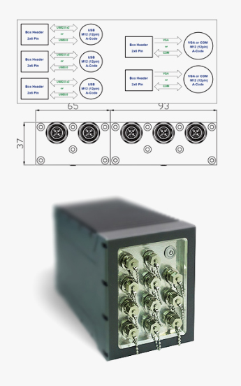
- Connectors M12
-
 During transport or in the field, unoccupied plug-in connections must be protected or closed. The screw plugs, sealing caps and closing caps made of plastic or metal are suitable for this purpose. IP65/IP67 protection as well as IP69 protection is thereby achieved.
Sealing elements with holding band or fixing chain
All IP67 interfaces can be closed tightly using the screw plugs and sealing caps in sizing M12. The holding bands are fastened on the cable or the hosing and are thus held captive. The M12 metal protective cap with fixing chain is suitable for all pin versions. It is used in harsh industrial environments or for EMC applications.
Assembly tools for actuator cables
To achieve tight plug-in connections, we recommend using assembly tools. M12 circular plug-in connectors can be assembled using a torque screwdriver and plug attachment. The benefits of the plug attachment become particularly clear when connecting the connectors to the distributor boxes. It enables quick adjustment and installation even when space is at a premium. The version for M12 connectors with hexagonal stainless steel knurl is also made from stainless steel, hence this prevents the connector knurls form being contaminated by corrosive materials. For greater flexibility, screwdrivers with adjustable torque are also available. When used in conjunction with the adapter insert, they can also be used to accommodate the available plug attachments.
- M25 MIL-DTL 38999
-
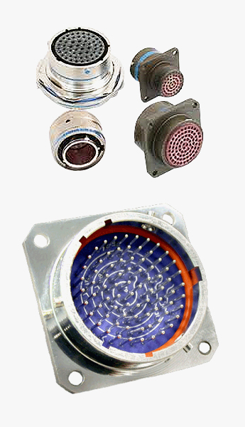 MIL-Qualified to MIL-DTL-38999 Connector offers a lightweight, corrosion resistant connector with the same high performance features as its metal counterpart. The Composite Tri-Start Connector also includes the following features:
• Lightweight - 17% – 70% weight savings(17–40% weight savings vs. Aluminum)
(60–70% weight savings vs. Stainless steel)See Composite weight comparison chart on page 23.
• Corrosion Resistance - available in standardMIL-DTL-38999 olive drab cadmium (-65°C to 175°C) and electroless nickel plating (-65°C to 200°C), both withstanding 2000 hours of salt spray exposure. The base material is able to withstand an indefinite exposure to salt spray.
• Durability - 1500 couplings minimum (in reference to connector couplings, not contacts)
• Extended Life Contact - Mil-approved plating process which provides 1500 couplings minimum
• Qualified to BACC63CT and BACC63CU specifications
General information |
Model | F1 |
|---|---|---|
| CPU Type | Intel® 3rd generation Core™ i7 Processor | |
| System Chipset | Intel® QM77 | |
| Memory type | 1 x DDR3 1333/1600MHz XR-DIMM 8 GB | |
Storage |
HDD/SDD support | 1 x 2.5” SSD |
| 1 x mSATA SSD backup storage | ||
I/O connectors |
Power button | 1 |
| VGA | 1 with M12 | |
| DVI | 1 with M12 | |
| Ethernet | 2 with M12 | |
| Audio | 1 with M12 | |
| COM | 2 with M12 | |
| USB | 2 with M12 | |
| DC-in | 1 with M12 | |
Mechanical |
Housing | Aluminum |
| Weight | 9Kg (19.84 lb) | |
| Dimension (W x H x D) | 147 x 172 x 268 mm | |
Power Requirement |
Input Voltage | 10V to 40V DC (Compliant with 28 VDC transient protections) |
Environment Limits |
Operating temperature | -40°C to 75°C |
| Storage temperature | -40°C to 85°C *without HDD installed | |
| Relative Humidity | Up to 95%RH @40°C, non-condensing | |
| Ingress Protection | Designed for compliance to IP65, MIL-STD-810G | |
TEST STANDARD |
EMI/EMC | Designed with 28 VDC transient protections |
| Military | Designed to meet MIL-STD-810G | |
| Vibration & Shock | Designed to meet MIL-STD-810G |
- CPU Performance
-
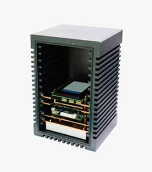
The F1 offers highly effectively heat conductive and heat convective thermal solutions to meet the demands of customers’ extended temperature requirements. The heat conductive solutions uses an aluminum flat mass to place in direct contact with the processor and chipset, the heat from chips then transfers it to the case of the system. In addition, the convective thermal solutions introduce airflow directed to move across the surface of a fin style heatsink placed on top of the processor and chipset. This can be done with the aid of an appropriately sized fan placed in top of the fin style heatsink. Alternately, enclosure airflow can be routed to flow across a fin style heatsink.
Device Model F1 Tester Ian Huang Test Result Pass Test Temperature High 0~75°C / Low -40~0°C Test Time 8Hours / 3Hours Test Standard Reference IEC60068-2 Test Software Burnin test v7.1,
Crystal DiskMARK3.03,
Intel Extreme Tuning UtilityCriteria After testing, system can't halt.
- Test Configuration
-
Device
Configuration
CPU
Intel® i7-3517UE 1.7GHz (17W)
PCH
Intel®QM77
Memory
4GB DDR3 1600 MHz XR DIMM
onboard SSD
Apacer 32G SATA SSD
SK401 MSATA PORT
Innodisk 64GB mSATA
SK401 2.5 in SSD
innodisk 2.5 inch 64GB SSD
Test Software
Burnin test v7.1、Crystal DiskMARK3.03,
Intel Extreme Tuning UtilityChamber
KSON THS-b4t-150 Chipeng SMO-3
- Thermal Measurement
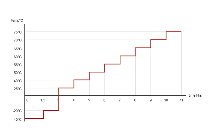
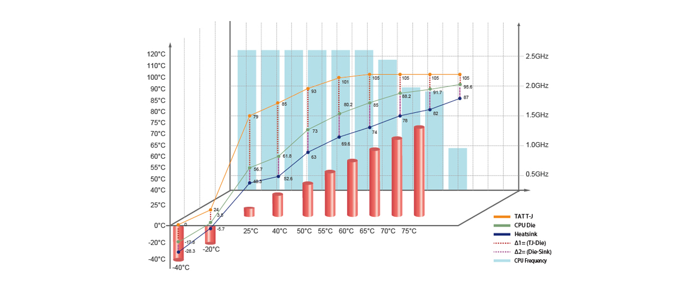
- STACKRACK provides real lab testing figures to show how CPU performance is with each tailor made thermal kits as important references and design guide for system engineers. For system integration, the crucial challenge is the operation performance under high temperature, thus STACKRACK conducts long time experiments to make sure the superior testing result for all critical missions. By revealing temperature at processor T junction, processor die and heat sink, STACKRACK is able to analyse the thermal solution we designed achieves maximum efficacy and observe CPU performance. The high temperature testing takes 5 hours which at each temperature point we burn in F1 for one hour, from -40 to +75°C.
- F1 MB HeatSink - IO Performance
-
Point
-40°C
-20°C
25°C
40°C
50°C
55°C
60°C
65°C
70°C
75°C
CPU T-J
0
24
79
85
93
101
105
105
105
105
CPU Die
-17.8
3.5
56.7
61.8
73
80.2
85
88.2
91.7
95.6
Heatsink
-28.3
-5.7
48.3
52.6
63
69.6
74
78
82
87
Δ1=(TJ-Die)
17.8
20.5
22.3
23.2
20
20.8
20
16.8
13.3
9.4
Δ2=(Die-HeatSink)
10.5
9.2
8.4
9.2
10
10.6
11
10.2
9.7
8.6
CPU Frenquency
2.59GHz
2.59GHz
2.59GHz
2.59GHz
2.59GHz
2.59GHz
2.39GHz
1.99GHz
1.79GHz
0.9GHz
Test Result
![]() mSATA DEMSR 64GB (Read) MB/s
mSATA DEMSR 64GB (Read) MB/s
![]() mSTAT DEMSR 64GB (Write) MB/s
mSTAT DEMSR 64GB (Write) MB/s
![]() 2.5" SATA SSD DES2S 64GB (Read) MB/s
2.5" SATA SSD DES2S 64GB (Read) MB/s
![]() 2.5" SATA SSD DES2S 64GB (Write) MB/s
2.5" SATA SSD DES2S 64GB (Write) MB/s
![]() On board SSD (Read) MB/s
On board SSD (Read) MB/s
![]() On board SSD (Write) MB/s
On board SSD (Write) MB/s
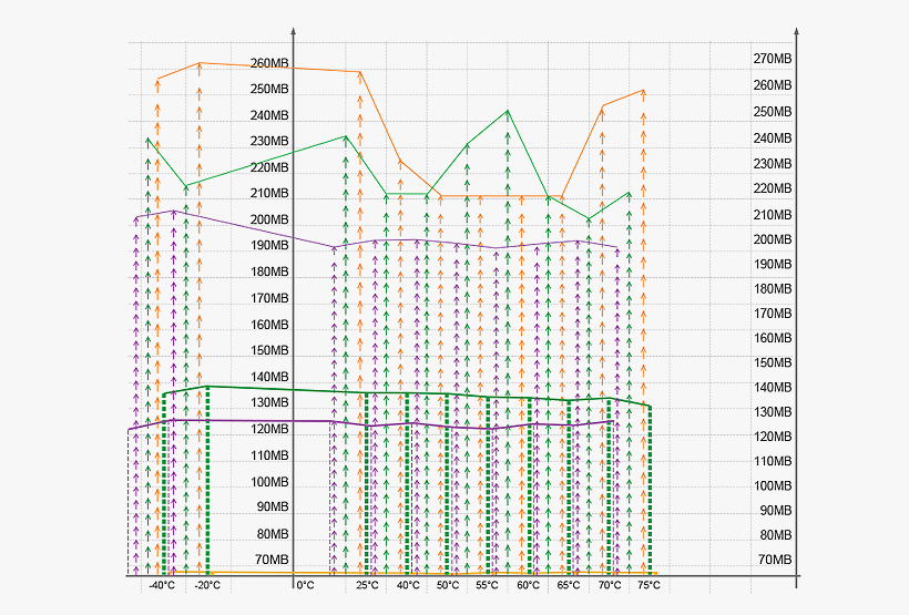
F1 MB HeatSink - IO Performance
| Point | -40°C | -20°C | 25°C | 40°C | 50°C | 60°C | 65°C | 70°C | 75°C |
| On board SSD (Read) MB/s | 256.8 | 263.4 | 259.9 | 235.7 | 221.4 | 221.5 | 221.5 | 256.3 | 262.5 |
| On board SSD (Write) MB/s | 49.62 | 49.32 | 48.41 | 48.78 | 48.53 | 47.84 | 47.73 | 47.75 | 48.03 |
| 2.5"SSD DEM2S 64G (Read) MB/s | 233.9 | 216 | 244.9 | 221.4 | 221.5 | 253.7 | 221.8 | 212.6 | 222.6 |
| 2.5"SSD DEM2S 64G (Write) MB/s | 137.1 | 139.2 | 137.4 | 137.5 | 137.2 | 135.9 | 134.3 | 135.8 | 131.6 |
| mSATA DEMSR 64G (Read) MB/s | 203.5 | 205.2 | 201.9 | 204 | 204.3 | 201.2 | 202.9 | 204.1 | 201.6 |
| mSATA DEMS 64G (Write) MB/s | 122.1 | 126.4 | 125.3 | 124.3 | 126.5 | 122.5 | 124.4 | 124.1 | 126.3 |
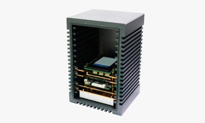
When StackPC meets ATR Structure…
ATR, which stands for Air Transport Rack, is a universal standard that determines the dimension and function of a rugged system especially dedicated to avionics/aerospace applications.
STACKRACK's Unique Solution
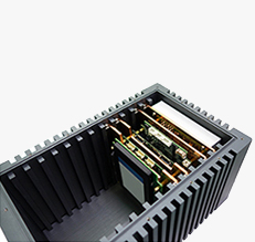
While usual ATR structure incorporates PCI, VPX, and VME based form factors, STACKRACK's F1-30 Conduction cooled ATR is powered by PCIe104 small form factor modules. PCIe104 – StackPC architecture provides even more flexibility in designing rugged COTS computers. Also known as ARINC, the concept has been used universally for not only aviation purpose but also vehicles with wheels and tracks.
- The Power of Conduction Cooling
-
STACKRACK, being the master of thermal design, has once again achieved fanless design through conduction cooling method. With each layer comes a heat plate to touch directly the heated parts, the thermal performance is of the highest level. The top side, which is designated as the customized I/O interface, is equipped with water/dust proof MIL-STD M12 connectors (enhanced D38999 by request).
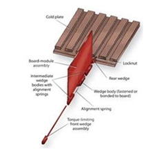
- CALMARK Wedge-Lok
-
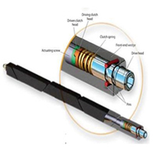
To ensure maximum reliability in rugged, heavy shock, and high vibration terrains, Wedge-loks from CALMARK can provide equally satisfying results. With 5 segments, shifted design, Wedge loks also help to transfer the heat and ensure best conductivity of heat load. The multi-segment design highlights on its ability to withstand massive vibration and shock, providing even higher sustainability through the torque-limiting design.
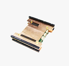
- Conductive Cooling Modules for Low/middle/high Power
-
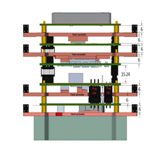
A solid material that can effectively conduct the heat is used to move the heat to the system enclosure and dissipated to the external surroundings. The machined copper cooling plates matching the component layout are placed between each layer; heat is carried away to the edges where a wedge lok mechanism secures inside the chassis, coming up with a thermal interface.
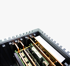
- Conduction Cooled Chassis Platform up to 10 Slots
-
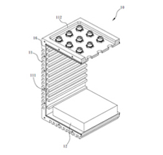
STACKRACK's ATR solution comes with an all-in-one design enclosure; each slot can securely fit a CALMARK wedge-lok, and each layer comes with a firmly attached, directly touched copper heat plate to complete a effectively cooled interior. What makes conduction cooling method so practical is that it is without moving parts, therefore suitable for high altitude and underwater applications.
- Aluminum Anodizing Enclosure
-
All-in-one anodizing aluminum chassis can withstand nuisance encountered in critical environments, such as dust and water.
- CNC Processed Fin-Type heat sink
-
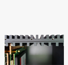
Heat sinks through CNC processed can provide large interface dissipating area. Acting as the thermal interface to transfer the heat to the surrounding environment.
- Aluminum Heat Sink
-
The heat sink is in direct touch with the power module. It can effectively transfer the heat from the CPU and PCH to the outer large surface heatsink. Aluminum extrusion design, tailored heat sink is capable of transferring the heat in the quickest and most effective fashion.
- CALMARK Wedge-Lok
-
CALMARK’s smart designed Wedge-Lok can transmit the heat from the heat plate and dissipate the heat to the outer heat sink. Five segment structures enhance the ability to function in rugged terrains.
- Layered Copper Heat Plate
-
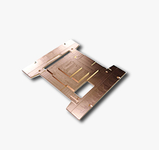
Machined cooling plates are placed between each layer, the mass and heat dissipation properties of the plates can effectively lower the operating temperature of the hottest components and average the heat from hotter to colder areas.